Sunbright Alarm Clock - Design
21 Aug 2014The idea is simple: a set amount of time before your alarm is due to go off the lights in the room are gradually raised to simulate dawn, thus leading to a more gentle awakening than the typical blaring alarm clock buzzer. In an ideal situation you would wake up just before your scheduled alarm time.
I saw this project on Hackaday which prompted action!
Design
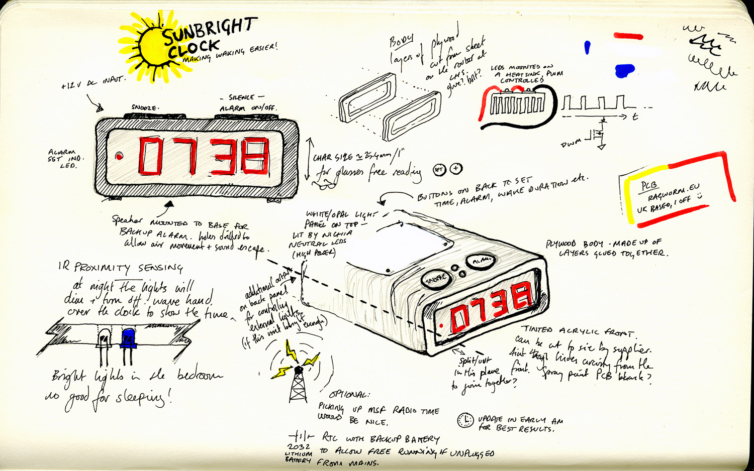
Before even looking at electronics for the build let's get this idea out of my head and into the real world using some pen and paper. This is what I came up with (click for the full size image).
First off, I wanted an end-grain plywood body/frame/case. This is mostly inspired by Mark Hennessey's Audax Monitor Speakers and a few odd pieces of furniture at work. I have recently become a member of Leeds Hackspace and know they have a few tools there that would help cutting a sheet of birch plywood with the appropriate openings. Each slice can then be glued together, (lots of clamps!) sanded and then sliced to create a top and bottom, for access. The split can be joined with a screw or two. Alternatively the front and back panels could be held on with screws - the internals sliding in from either end.
Tinted acrylic for the front. The grey tint will allow the 7 segment LED displays to be seen whilst hiding the PCB and things. The PCB might need to be spray painted black for the best results.
For the actual waking light a translucent opal panel (this might have to be sanded clear plastic, depending on the brightness) on the top would be light by two or three Nichia neutral white high brightness LEDs. These are very good - I've used one in the microscope conversion and another in a bike light and they are great. The bike light in particular is bright at only 700 mA. Two at a higher current (probably around 1.4 amps) should be suitable.
In case these two LEDs aren't sufficient to wake my heavy-sleeping partner I propose an additional output of the PWM signal that can be utilised by an external light controller. I don't really want to do this as it will be a bit messy, but it's better than the thing not working as well as it could! I have an advantage in that the room this is intended for has blackout curtains, so any light at all is immediately noticeable.
Having lived with the Digital Logic clock for a while now I've come to the conclusion that the LEDs are too damned bright, even though I thought I took this into consideration when designing it. For this reason once the lights are out in the room the display will slowly fade out to nothing, only turning back on when waved at.
Circuit & Components
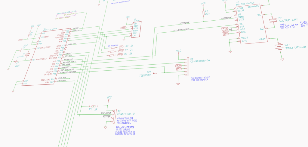
The microcontroller running the show is the venerable ATmega328 - typically used in the Arduino. It's powerful, easy to find and most importantly I have experience programming it with both Arduino libraries and more down-to-earth C.
Maxim's DS1305 will be used for the RTC as it has an SPI communication mode - I find SPI easier to work with on the AVR chips, and besides rocketnumbernine has a handy library that with a bit of customising should take care of most of the grunt work. Maxim also make the MAX7219 which I will use to control the 7-segment display. I've used this chip before, so I will just modify that existing code to make it more portable and to sort out some quirks.
Helpfully both of these devices deviate from the SPI standard slightly by having chip select pins that need a high signal to make them work.
I want the option of getting time for the UK radio time service, MSF, so an interrupt pin is left open to accommodate that. Code wise this might be a bit of a challenge, so let's see how that goes. As usual, extra unused pins will be broken out to make future expansions easier although this time I will be putting dedicated VCC and GND connections for each of the three remaining analog pins.
LEDs
I want brightness, but I also want controllability and simplicity. The LEDs will be arranged in series and fed a constant current by an LM338 at 12 volts. The LM338 works identically to the LM317 but is capable of sourcing 5 amps of current continuously, with peaks of 7 amps possible - this would of course require some serious thought with regards to how to heat sink the TO220 package!

Illumn supply the Nichia LEDs on electrically neutral metal backed PCBs which can simply be attached to a suitable heat sink with thermal compound. I will be choosing the size and form factor for the chunk of metal I'll be attaching these too once the rest of the case and circuit starts to take shape.
OK? Let's go!
The parts have arrived, so now it's time to get started with breadboarding this mess.
I learnt from last time that prototyping discrete chunks of a circuit in isolation doesn't always work well. I've already created most of the schematic in KiCad, so it is just a case of transferring this to a breadboard (join the dots...) and see if it works, then fixing and updating the bits that don't go quite to plan.
Useful Links
Places
Inspiration
- Hackaday - Extrinsic Motivation: Integrated Room Sunrise Simulator
- Mark Hennessey - Audax Mini-Monitors
- adnbr - Upgrading a microscope to LED illumination