Upgrading a microscope to LED illumination
18 Aug 2013I recently managed to save a big, heavy binocular microscope from being rather unceremoniously turned into scrap metal. After spending a fair while looking at anything we could put our hands on underneath its' lenses I turned to changing the dim yellow tungsten light bulb to something with a bit more oomph - a high brightness LED.
The eventual aim is to attach a camera to it, so more light is always better.
There is a GitHub repository for this project, should you want any of the project files.
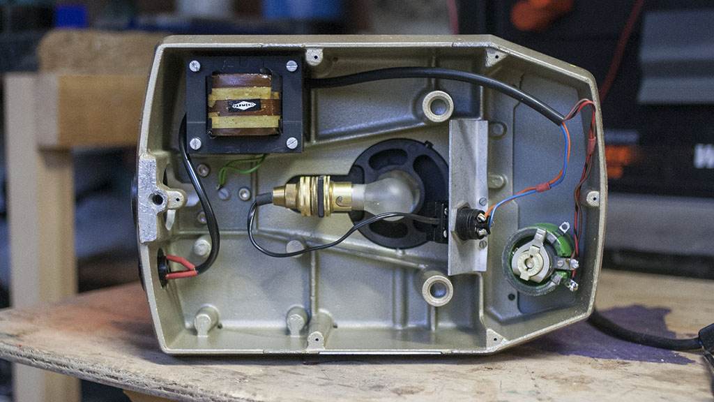
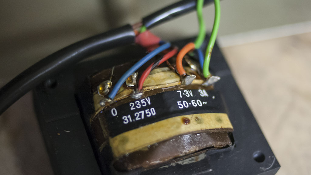
Removing the base we can see the knob that controls the brightness is wired to the transformer - after many, many years of use it is very gritty, worn and not smooth at all. Turning the dial feels horrible in the hand. I think that this knob is a variac, but I'm not sure. As the knob is turned the voltage coming out of the secondary winding of the transformer is altered - moving from a low of 3 volts up to a high of 7.0 volts.
This will be removed and replaced with a modern, smooth turning carbon film potentiometer handling only small 5 V signals rather than the mains of the old. The new potentiometer will feed the ADC input of an ATtiny13 micro controller which in turn controls the brightness of the LED through PWM.
I want to keep the external look of the microscope the same, so the potentiometer has been specially chosen so that the existing knob fits into the shaft.
The circuit design
The circuit is simple - A bridge rectifier and capacitor converts the AC from the existing transformer into DC that the MCP1826S voltage regulator can work with. The MCP1826S is used instead of a bog standard 7805 because of the super-low dropout voltage of at most 400 mV, or 0.4 V. The bridge rectifier will drop the voltage quite significantly (by 1.1 V or so) and I want as much head room as possible to get a clean 5 V from the rectified transformer output. This LDO voltage regulator can also supply up to 1 A of current, allowing a super-bright LED if it is needed.
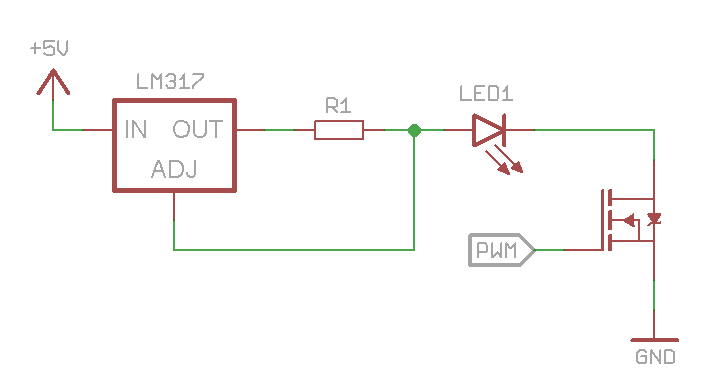
A basic constant current driver built from an LM317 adjustable regulator and an appropriately sized resistor provides power to the LED, which is pulsed on and off at high speed according to the whim of the ATtiny13, enforced by a 2N7000 mosfet.
The LED I am using can draw over an Amp without breaking a sweat - ridiculously bright (way too bright to be looking at through a lens) so I'm limiting it to approximately 550 mA with a handy 1 W 2.2 Ω resistor I have in my odds and ends box.
I opted to send this PCB to OSHPark and have it made by someone who knows what they are doing. The layout is single sided with fat traces and loose tolerances so on the off chance that someone wants to etch this at home themselves they can. There are three traces on the top layer but these are solely for 'spare' pins not necessary for standard operation; they are simply for future proofing. Design files can be found on GitHub.
Having thought about the choice of mosfet the 2N7000 is definitely optimistic. The circuit on the breadboard works but the mosfet is definitely passing way more current than it is designed to and probably being damaged by doing so. When the boards arrive from OSH Park I will have to try mounting a different part, such as a ZVN4306A, which is has a maximum current rating of 1.1 Amps at a gate voltage of 5 V.
The LED and light diffuser
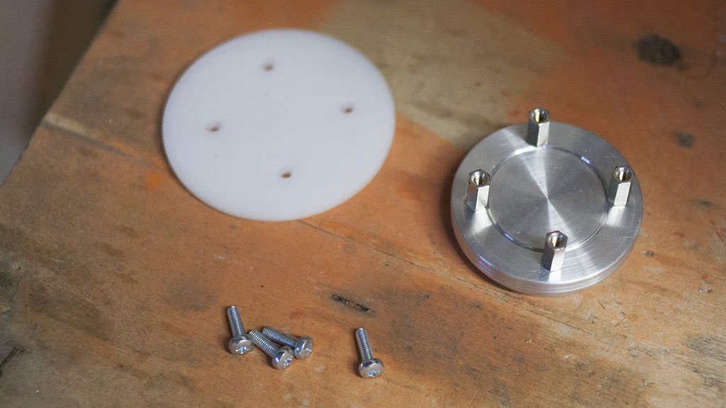
The LED itself resides on an aluminium puck - a kind of oversized heat sink - turned from a piece of scrap aluminium I had lying beside the lathe. I'm not too worried about the heat production so I didn't bother with any radiator fins. If you can look carefully you can see the dent on the edge where I dropped it onto the concrete floor of the garage.
To get the best image the light source should be diffused - otherwise there is the possibility of an image of the LED die or bulb filament becoming a part of what you are viewing through the lens. For this I will be using a 3mm thick sheet of opal acrylic mounted on top of the heat sink by way of four M3 screws and spacers. Diffusing the light will also give a larger apparent light source - probably not too important here, but why not?
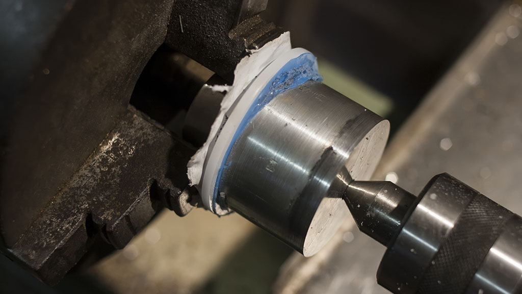
First the acrylic was trimmed to a rough circle using a hacksaw and then mounted in the lathe using a live centre in the tailstock and a spare cylindrical chunk centre drilled to push against the work. In the chuck there is a piece of aluminium shaped like an inverted top hat holding the acrylic in place. Both the front and back holders are stuck to the plastic film covering of the workpiece with superglue.
In retrospect, this could have been a bit more secure and the plastic could have been a bit more circular before I started to help balance the lathe, although the way I cut it (a sort of bodged trepanning) didn't really require a circular starting point. Also, attaching to the plastic film covering was sort of a good idea, but as you can see in the image above didn't quite hold on securely. In the end it was just the friction of the tailstock pressing against the work that stopped it falling off/flying across the room. That is what it's there for I suppose...
Slowly the piece is turned down to a circle making sure that there is enough room near the edges to drill the mounting holes. Acrylic is brittle and is prone to cracking when a hole is drilled near the edge. In this case, I made the final diameter 60 mm. The edge is lightly sanded with wet & dry paper to give smooth finish.
With the diffuser attached to the top of the heat sink with a small amount of double-sided tape four 3 mm holes are drilled through the acrylic and into the heat sink just enough to leave a mark to locate the 2.5 mm drill for the M3 through-hole tap. The through holes will be used to mount both the diffuser to the heat sink and the heat sink to the base of the microscope and once in place the diffuser should sit at around the height of the old filament bulb.
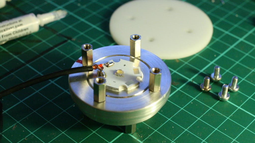
When soldering the wires to the high-powered LED do it before you attach the heat sink with thermal adhesive or you may find, like I did, that the large lump of aluminium does its job rather too well and makes soldering a much more time-consuming affair than normal.
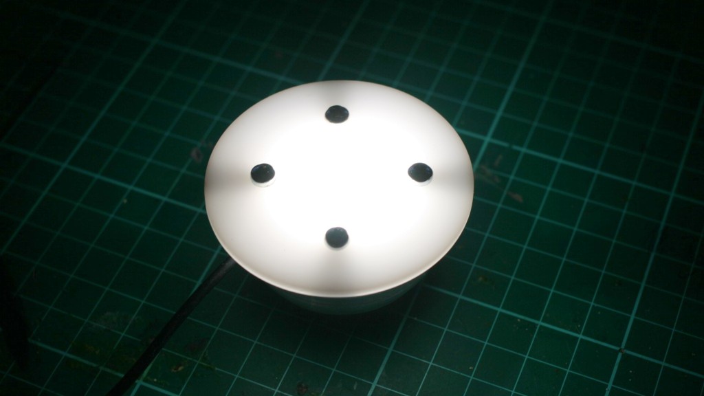
Having run the LED for 10+ hours I am pleased that it barely gets warm, let alone hot enough to be near the 150 degree maximum junction temperature. The LM317 regulating the current gets a little warmer but it is well within operating limits - the tab on the TO220 package can be comfortably held for an extended period of time without discomfort.
And with the light source mounted to the base of the microscope it's time to write the code for the ATtiny13 while waiting for the PCBs to arrive from OSHPark...