Counting milliseconds
21 Apr 2012The Arduino libraries make use of a handy function to track milliseconds, known as millis(), but looking briefly at the code that makes it up there seems to be a lot of other code intertwined throughout.
I want to learn to program AVR devices properly using C, not the easy way with Arduino so I thought this would be a good opportunity to implement millis() on my own as no doubt I'll be using it a lot when counting down delays in the future.
Timer Compare
I will be letting the AVR hardware timers do most of the work here, and make them trigger an interrupt whenever the timer equals one millisecond, or 1/1000th of a second. Working out how many 'ticks' of the timer is equivalent to a millisecond is easy, we simply need to divide the clock by 1000, and then by a suitable prescaler to get a round, even number. <!--more--> The 16 MHz crystal on the Arduino board makes this easy - 16 MHz divided by 1000 is 16 KHz, which divided by a handy prescaler of 8 gives us 2000. So, every time the Timer counter equals 2000, a millisecond has passed and it would probably be a good time to update the 'millisecond' count.
This can all be handily condensed into a preprocessor macro, and will work accurately as long as you take the time to check that your crystal will divide cleanly.
#define CTC_MATCH_OVERFLOW ((F_CPU / 1000) / 8)In the setup section of your code you can now assign this value to the comparator registers. We will be using Timer1, which is 16 bits, so the register is split over two 8 bit bytes. We therefore need to shift bits in order to assign the "High" byte.
// Load the high byte, then the low byte
// into Output Compare A on Timer 1
OCR1AH = (CTC_MATCH_OVERFLOW >> 8);
OCR1AL = CTC_MATCH_OVERFLOW;
We can see from page 133 of the datasheet that setting the CS11 bit of the TCCR1B register will set the timer input to the system clock, divided by 8. That's what we want, along with WGM12 (page 132) to enable the OCR1A Clear Timer on Compare match (CTC) mode so let's set those bits.
// CTC mode, Clock/8
TCCR1B |= (1 << WGM12) | (1 << CS11);
Finally, let's enable the interrupts before we get onto the interesting stuff. Remember that you need to include the interrupt header file with #include <avr/interrupts.h>
// Enable the compare match interrupt
TIMSK1 |= (1 << OCIE1A);

// Now enable global interrupts
sei();

// Set PC0 to an output, we'll be using
// this from our interrupt
DDRC |= (1 << PC0);
The Interrupt Service Routine (ISR)
I used to be scared of interrupts, treating them in a way similar to threads on larger desktop machines. Something to keep at arms length as much as possible. They're actually really simple though, and nothing to be concerned about at all - the key is to keep everything as short as possible - especially if you consider that this will be called 1000 times a second.
You can find a list of the interrupt vectors (the events that can cause an interrupt) and their names on the AVR-Libc website. If you are using a different compiler, I think they might differ.
ISR (TIMER1_COMPA_vect)
{
    // Toggle PC0 (Arduino's Analog 0)
    PORTC ^= (1 << PC0);
}
This simple, short ISR simply toggles PC0 every time the interrupt is called creating a square waveform which can be seen on an oscilloscope quite nicely.
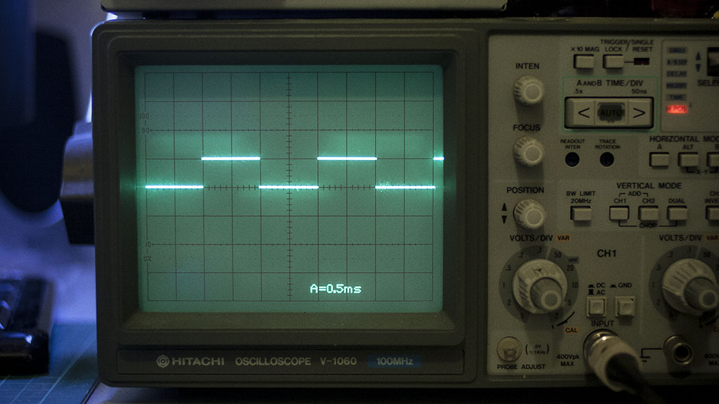

In this image, it can be clearly seen that the value is changing every 2 blocks, or 1 millisecond. I chose the 0.5 ms vertical division to see with a bit more resolution how accurate the timing is. With the CRT intensity turned down low it is very easy to see that the periods last for almost exactly 1 ms before changing, there is none of the overlap shown in this photograph.
It works!
Great! It worked first time around! We're not quite finished though. If we wanted to simply output a square wave onto a pin we could have done everything in hardware and not had any interrupts involved (look up the "Compare match output unit" in the datasheet if you're interested) at all, but that's not what we want.
If we introduce a variable to hold the millisecond count then we can simply increment that every interrupt and then read it when we call millis().
volatile unsigned long timer1_millis;Because the variable is called in an interrupt it must of course be declared as volatile. This tells the compiler that the value is likely to change at any time, and prevents it from being optimised away when it isn't used in the "normal flow" of the application. The unsigned long allows the counter to tick for some 49 days before it overflows to zero.
So, our new ISR looks something like this;
ISR (TIMER1_COMPA_vect)
{
    timer1_millis++;
}
We've got rid of the flashy output - we don't need that any more now that we've confirmed that the duration really is one millisecond and it will just eat up space (and time) in our ISR otherwise.
Creating millis()
So far our code looks like this:
#define F_CPU 16000000UL // 16 MHz

// Calculate the value needed for
// the CTC match value in OCR1A.
#define CTC_MATCH_OVERFLOW ((F_CPU / 1000) / 8)

#include <avr/io.h>
#include <avr/interrupt.h>

volatile unsigned long timer1_millis;

ISR (TIMER1_COMPA_vect)
{
    timer1_millis++;
}

int main (void)
{
    // CTC mode, Clock/8
    TCCR1B |= (1 << WGM12) | (1 << CS11);

    // Load the high byte, then the low byte
    // into the output compare
    OCR1AH = (CTC_MATCH_OVERFLOW >> 8);
    OCR1AL = CTC_MATCH_OVERFLOW;

    // Enable the compare match interrupt
    TIMSK1 |= (1 << OCIE1A);

    // Now enable global interrupts
    sei();

    while (1)
    {
        // Forever
    }
}
And it has done everything it has set out to do. It increments a variable which can then be used anywhere in the main program.
There is a problem with this however, and it involves the interrupt we are invoking every 2000 clock cycles.
Because the interrupt can literally be called at any time and the microcontroller will drop everything to service it there can sometimes be problems reading 16 bit (and larger) variables that might be modified, thus leading to unreliable values and therefore unreliable code. This is I think (roughly put) because the AVR hardware doesn't support reading the appropriate storage register in one movement because it is at heart an 8 bit system.
It is simple to stop this from happening by declaring sections of code as "atomic" using the macros AVR-libc's library provide, which essentially wraps the encompassed code in more code that briefly disables and then re-enables interrupts to allow unimpeded access to large variables.
To make such "atomic" code easy to access, we can wrap it all up in the friendly and easy to use millis function. Be sure to include atomic.h so the compiler can find everything it needs.
unsigned long millis ()
{
    unsigned long millis_return;

    // Ensure this cannot be disrupted
    ATOMIC_BLOCK(ATOMIC_FORCEON) {
        millis_return = timer1_millis;
    }

    return millis_return;
}
That is that, pretty much done. As a quick example, we can use the new millis() function to toggle an LED every second. You could use _delay_ms() to achieve this functionality but of course that would prevent the microcontroller from doing anything else while it was waiting.
Add back the code that declares PC0 as an output:
DDRC |= (1 << PC0);Now we can flash that every second using a global variable, milliseconds_since.
void flash_led ()
{
    unsigned long milliseconds_current = millis();
    if (milliseconds_current - milliseconds_since > 1000) {
        // LED connected to PC0/Analog 0
        PORTC ^= (1 << PC0);
        milliseconds_since = milliseconds_current;
    }
}
As previously mentioned implemented in a non-blocking manner, meaning that the processor can continue doing other things while it is waiting for the appropriate time to pass. Handy.
Done.
And that's it, really. If you don't want to use Timer1 elsewhere in your code this is a really simple way to literally count the seconds as they go by.
As per usual, the final code is available to grab from Gist.