MAX7219 and 7-segment displays
10 Apr 2012Maxim's MAX7219 and MAX72221 chips are really rather handy when it comes to controlling a collection of 7-segment LED displays. They are also quite useful when it comes to controlling up to 64 individual LEDs when appropriately arranged.
The main library I found was LEDControl which seems to work for most people, which is great, but it wasn't doing anything for me. After playing around with it for a while I decided I would go my own way and write my own code to interact with it, without the Arduino support structure.
After taking a look over code by Bob Carret I had an idea where to start. I will be writing my code to work on the ATMega168 chip as that is what I have in the Arduino development board with a view to making it more universally compatible later on.
Hooking it up
To be honest, I don't think I can do better than the 'Typical Application Circuit' from the datasheet, so I would suggest you take a look there for a circuit diagram.
In my case I'm using a small custom PCB because the display will eventually be mounted in a case. I had Laen make them using his DorkbotPDX PCB service, which is definitely worth a look if you have bad luck with proto/strip board (like me) or you have a complicated design.
What I am going to touch on though is the selection of RSET to appropriately set the maximum current per segment. You absolutely must refer to Table 11 on Page 11 of the datasheet when choosing the resistor for RSET as it will definitely be bigger than you would normally expect.
The minimum is 9.53kΩ, and in the case of the 7 Segment displays I am using, is a meant to be at least 17kΩ. The consequences for choosing an incorrectly sized resistor is the same as with normal LEDs - damage leading to failure. It is however much more devastating as once a segment is blown, the entire display is practically useless.
Remember to include the typical 0.1µF decoupling capacitor, alongside an extra 10µF capacitor. The larger is definitely required, without it the display can sometimes display gibberish or stop working altogether from the massive ripples in the power supply caused by the PWM brightness control.
Talking the talk
The MAX7219 chip communicates with a protocol based on SPI, with 16 bits per instruction. It's one directional as the chip never has anything to tell you, so we don't have to worry about receiving data.
The first byte is the register you are selecting, which could be either a command register (such as the one controlling the brightness, or the decode mode) or the address of the digit you wish to alter and the second byte is the data you are sending to it.
The following code snippets are set for an ATMega328 chip, but you can update them very simply to be more appropriate for your chosen AVR microcontroller.
First, we define the ports and register bits we will be using - these must be the defined SCK, MOSI and SS pins for the chip you are using.
// Outputs, pin definitions
#define PIN_SCK  PORTB5
#define PIN_MOSI PORTB3
#define PIN_SS   PORTB2
Then set the Data Direction bits for these pins, setting them all to 1, or Output. If we were receiving data as well then we would include MISO and set it to 0, or Input.
// SCK MOSI CS/LOAD/SS
DDRB |= (1 << PIN_SCK) | (1 << PIN_MOSI) | (1 << PIN_SS);
Now that the boring stuff is out of the way we can get on with setting up the AVR for SPI transfer by altering the SPCR register.
// SPI Enable, Master mode
SPCR |= (1 << SPE) | (1 << MSTR) | (1 << SPR1);
Here we are setting the SPI Enable bit SPE and the Master bit MSTR which controls whether the SPI hardware interacts with the bus in a manner befitting a Master or Slave.
The MAX7219 should be able to cope with SPI clock speeds of up to 10MHz but I've never had much luck running it at anything near that. Settling into a nice, steady SPR1 controlled 1/64th of the clock frequency works quite nicely though, so we'll stick with that for the moment.
Right, so the SPI hardware is set up and we want to transmit data.
void spiSendByte (char databyte)
{
    // Copy data into the SPI data register
    SPDR = databyte;
    // Wait until transfer is complete
    while (!(SPSR & (1 << SPIF)));
}
Simple copy a byte of data you want to transmit into the SPDR register, and wait for the SPIF bit of the SPSR register to be set to indicate that the transfer is complete.
Yes it's really that simple. There are a few more steps, such as pulling the chip select line low but we'll get to that in a minute.
Making the MAX7219 listen
With the code above you could merrily send data all day if you wanted and not a thing would happen. The load pin on the MAX7219 hasn't been set low to make it listen.
#define MAX7219_LOAD1 PORTB |= (1 << PIN_SS)
#define MAX7219_LOAD0 PORTB &= ~(1 << PIN_SS)
These defines are pre-processor macros, or shortcuts - calling LOAD1; will set the pin high and LOAD0; will set it low.
void MAX7219_writeData(char data_register, char data)
{
    MAX7219_LOAD0;
        // Send the register where the data will be stored
        spiSendByte(data_register);
        // Send the data to be stored
        spiSendByte(data);
    MAX7219_LOAD1;
}
Combine these with the spiSendByte function and the MAX7219 will start listening to what we have to say, and will actually act on it.
The registers are all referenced in a convenient hexadecimal format, so all you have to do is read the datasheet to find what you need.
Simplifying matters
Because the registers are fixed, it is easy to create a few pre-processor #defines to keep track of them. For example, here are the command registers:
#define MAX7219_MODE_DECODE 0x09
#define MAX7219_MODE_INTENSITY 0x0A
#define MAX7219_MODE_SCAN_LIMIT 0x0B
// POWER is actually the SHUTDOWN register,
// but this works better semantically
#define MAX7219_MODE_POWER 0x0C
#define MAX7219_MODE_TEST 0x0F
#define MAX7219_MODE_NOOP 0x00
To switch the display into test mode it is simply a case of sending the correct register followed by the on code, 1, through the writeData function. While we're at it, let's turn on the 'power' so that the display lights up.
MAX7219_writeData(MAX7219_MODE_TEST, 1);
MAX7219_writeData(7219_MODE_POWER, 1);
And to turn off test mode, simply write 0 to the MODE_TEST register.
MAX7219_writeData(MAX7219_MODE_TEST, 0);It would be more easily read if 1 and 0 actually meant anything, so from now on we'll be using a couple of new pre-processor definitions to refer to them as ON and OFF.
The individual digits also get the same treatment as the registers, and can be given their own pre-processor shorthand to make accessing individual digits easier.
#define MAX7219_DIGIT0 0x01
// ...
#define MAX7219_DIGIT7 0x08
Because the individual digits are referenced in the same way as a command register displaying a number is as easy as turning on the power, or setting the brightness.
MAX7219_writeData(MAX7219_DIGIT0, 7);Wait, that's not what I said to happen...
You may find that when you write the data to the digit it doesn't quite display what you thought it might, and will probably end up looking like the image below. That's because it probably isn't in the right decode mode, and is instead simply showing you the binary code of the digit you sent.
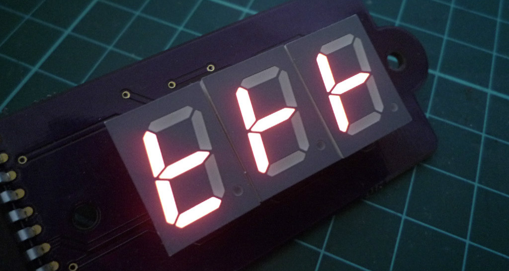
If you had LEDs lined up in a row instead of in an 7-segment pattern it would make sense, but that's not at all helpful in this case. In the above image the digits are meant to be displaying "77".
What we need to do is set the decode mode to the Code-B font required by 7 segment displays using the MODE_DECODE command register.
MAX7219_writeData(MAX7219_MODE_DECODE, 0xFF);There are several options for this, involving decoding for some, all or none of the digits. This is well explained in the datasheet along with the functioning of the rest of the registers.
If you are having trouble displaying digits on anything other than DIGIT0, look into the Scan Limit command, which controls which digits are turned on for display.
MAX7219_writeData(MAX7219_MODE_SCAN_LIMIT, 3);The number of digits in use (even if they are blank) will affect the brightness of the display, so if you need slightly more than 8 digits try to divide the load evenly, i.e. 6 digits each on two displays rather than 8 on one and 4 on another.
To save processor time when you are using only a few digits it might be worth implementing a variable to hold the current scan limit (the chip can't tell you) and then use that when clearing the display or cutting up integers.
Writing a full number
Writing single digits to the display is all well and good, but it doesn't help much in the real world. We need a way to break down an integer and get it out there to make this chip really easy to use.
Unfortunately the MAX7219 doesn't offer this functionality, so we need to roll our own. Let's start with clearing the screen.
The Code-B font the chip supports 15 characters including blank (a quick reference is on page 8 of the datasheet) which quite handily tie up with the base ten decimal numbers. In other words, if you write an integer 4 to a digit it will display 4. Handy.
In this case we want to clear the screen, by setting every digit to 0xF. Let's quickly add a pre-processor define for clarity, then implement a function.
#define MAX7219_CHAR_BLANK 0xFIf you remember previously I mentioned using a variable to keep track of the scan limit - this is where it comes in handy. Clearing all eight digits takes quite a significant amount of processor time - first sending the digit address and then the digit contents and waiting for that all to filter out of the SPDR register, so if we aren't using them all, why bother?
void MAX7219_clearDisplay()
{
    unsigned char i = digitsInUse;
    // Loop until 0, but don't run for zero
    do {
        // Set each display in use to blank
        MAX7219_writeData(i, MAX7219_CHAR_BLANK);
    } while (--i);
}
Now that it guaranteed that the screen will be clear, we can move on to displaying a number.
Splitting an integer into its component digits it can be a pain if it is negative - therefore, we multiply by -1 if it is less than 0. We'll make a note of whether it is negative though, and we can come back to it later to display the negative/minus symbol.
unsigned char negative = 0;

if (number < 0) {
    negative = 1;
    number *= -1;
}
Also, if the number is zero we can simply display a single zero and be done with the matter.
This next section deals with actually splitting the number up into component digits. It works by taking the modulo of the number against 10 (the remainder after dividing by 10) and displaying that, and then actually dividing by 10 to move to the next digit, all the way down until it reaches 0. Because the divide by 10 is not a floating-point operation, the remainder is discarded.
unsigned char i = 0;

// Loop until number is 0.
do {
    MAX7219_writeData(++i, number % 10);
    // Actually divide by 10 now.
    number /= 10;
} while (number);
It's as simple as that. A quick check to check if the input number was negative (if you wish to display the sign) and away you go. Check the Gist code for specific details on how to do this.
Something that might be worth checking is if the input number is too big to display on the screen. On my 3 digits the maximum I can show is 999, so I might throw in some extra code to show an overflow message or prevent values ever getting that high. If you have a larger number of segments available you will of course be able to display much larger numbers.
OK, that's enough for now
I hope found this post useful, it's meant to serve as an introduction to both the MAX7219 and the SPI hardware on the AVR chip as well if you haven't used it before.
Downloads
You can copy the AVR C code for this article from Gist.