One Day Project - UV Index Indicator
02 Jun 2017One of my favourite parts of art school was the infrequent "one day brief", in which everyone would turn up early in the morning, be given a project to work on for the day, and then hand in work for presentation that evening. Rather than deliberating and procrastinating for weeks over a longer term project it was a good opportunity to just get out here and actually do something.
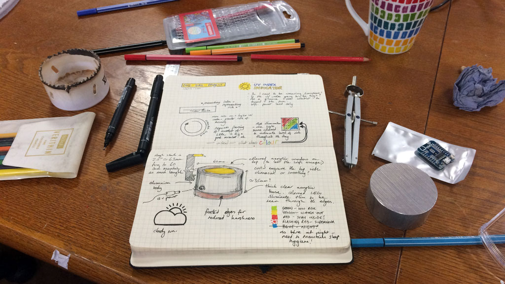
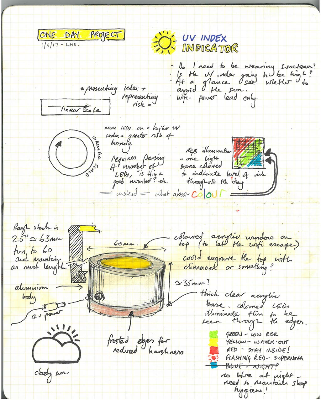
In that spirit, I booked yesterday off work with the aim of starting and completing a project in one day, utilising the facilities of Leeds Hackspace. The weather has actually been quite nice recently, so I decided to make a simple device to indicate when it was most dangerous to be in the sun - a visual representation of the UV index for Leeds - as I've found myself getting close to catching the sun when walking home from work.
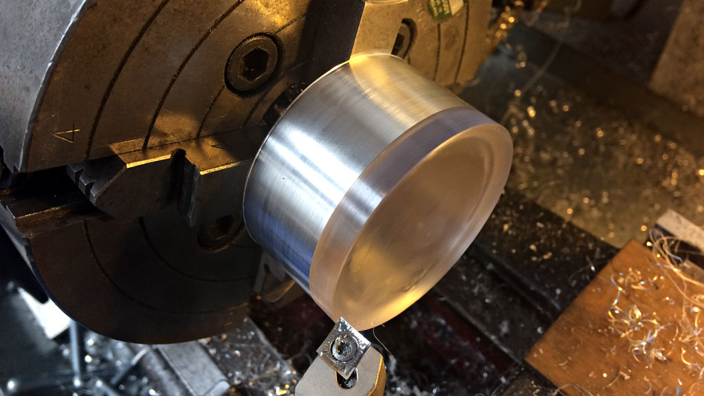
I had a 2.5 inch (~64 mm) diameter chunk of aluminium, just over an inch (~27 mm) long which would become the main body. It would have been nice to start with some heavy walled tube instead to reduce material wasteage (the pile of swarf produced was quite impressive) but this is all I had knocking around.
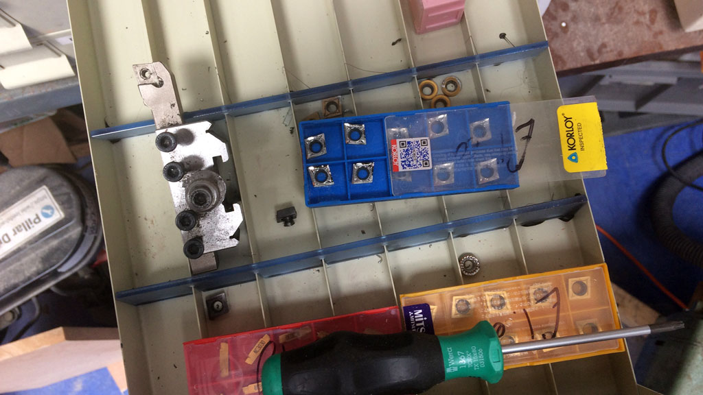
The only insert in use was a CCMT style one suitable for use with steel, so it was time to break open a new pack of CCGTs. These ones are from China, Aliexpress, so who knows if they actually are Korloy. They were cheap though, and they work well.
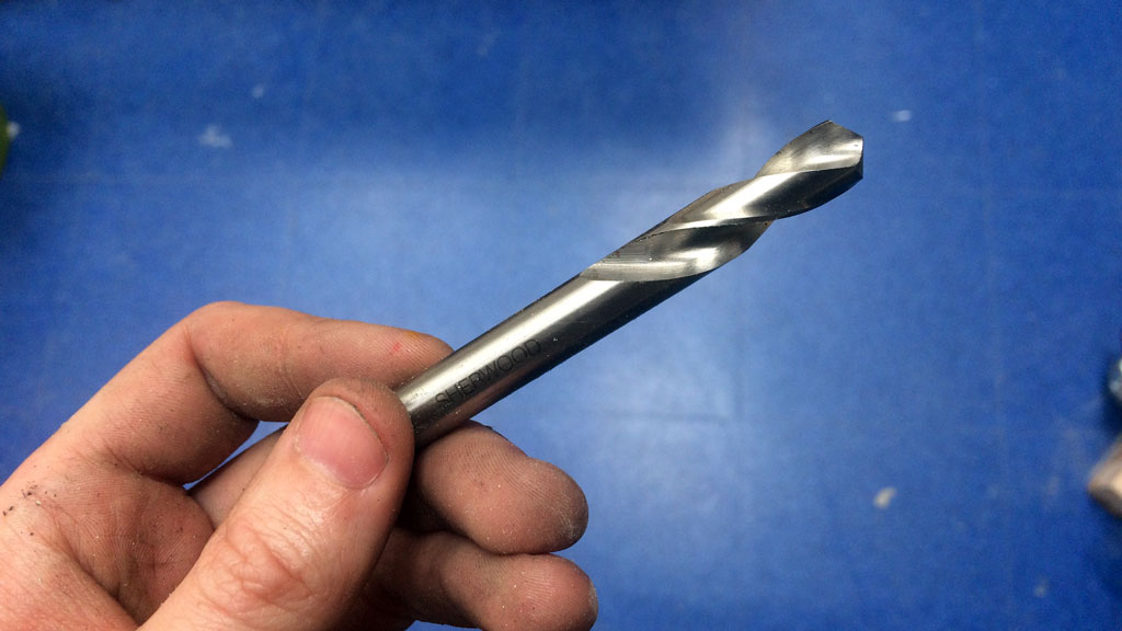
Once the material was faced square the central hole needed to be started. A short, stubby spotting drill creates a point best suited for starting a drilled hole - much better than a centre drill - and stub drills keep flex and bending to a minimum. There's not much need for a particularly accurate drilled hole here the centre will be bored out to dimension, but it's good fun using these short little drills instead of the cheap and nasty assortment bits.
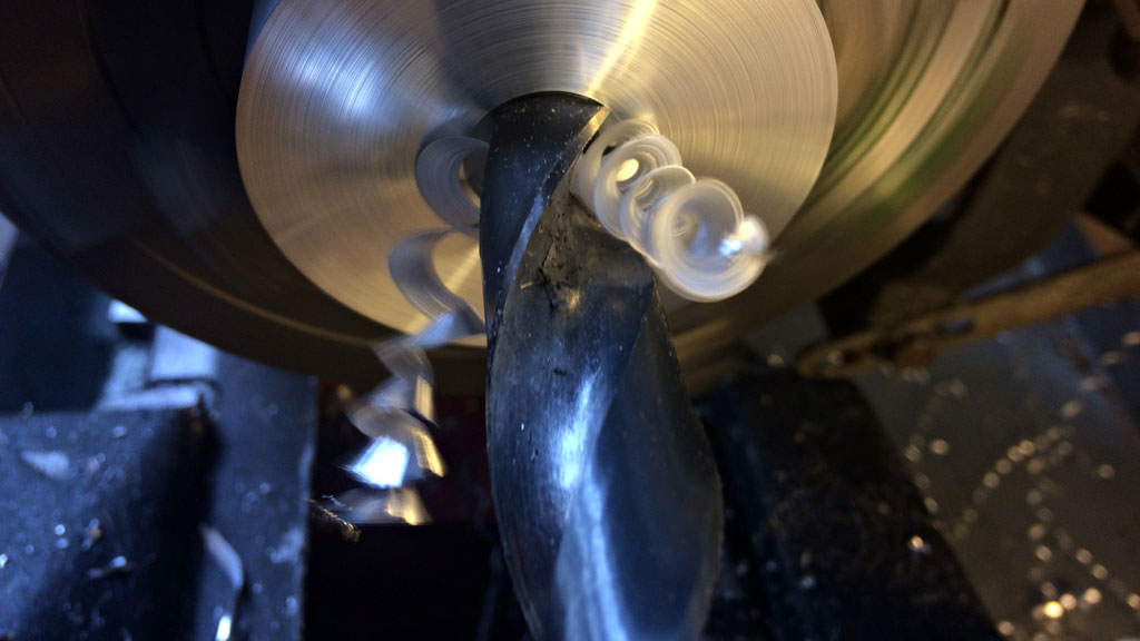
After working my way up to 10 mm (Spot drill then 5 mm stub) it was time to slow the spindle speed right down and jump in with an 18 mm MT2 drill. Cutting just enough material to clear the web of the next size up saves time and maintains an even wear on all of the cutting edges, although it does need a bit more oomph in your machine.
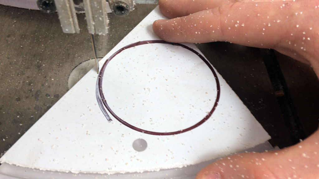
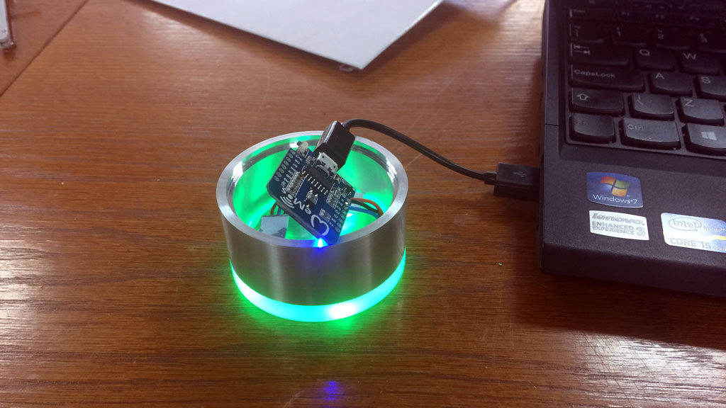
With the hole bored out to size, including a small step to hold the top cover, it was time to sort out the diffusing light base. I found some scrap 10 mm thick clear acrylic on the shelf, drew around an approriately sized hole saw and then rough cut the circle on the band saw.
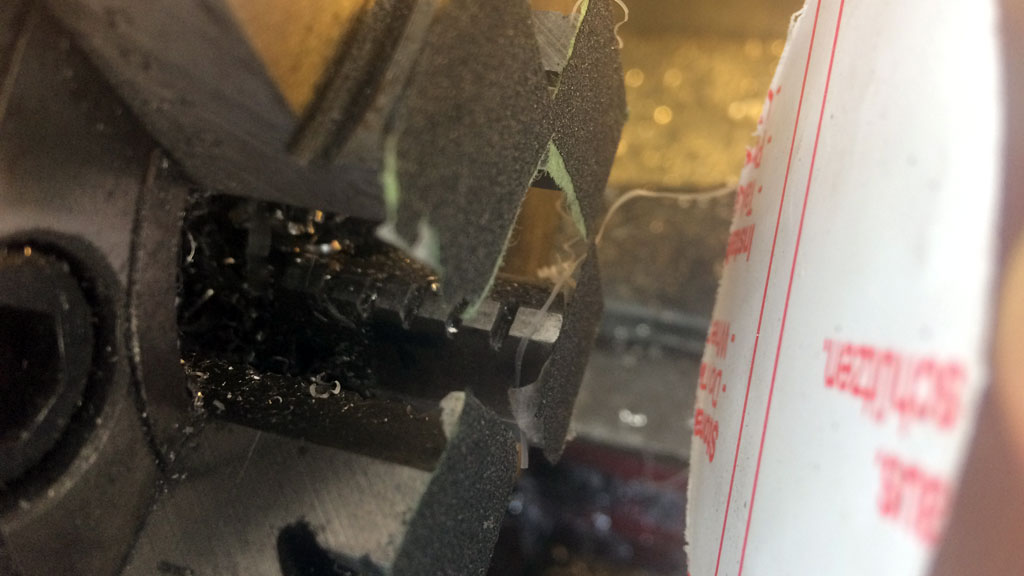
I pressed the rough cut blank against the front face of the chuck jaws with a live centre, ensuring that it didn't slip under the cutting forces by sticking a small amount of sand paper to the chuck with double sided tape.
The surface of the acrylic wasn't protected from the live centre because preserving the surface (which would be hidden inside the finished product) wasn't a requirement, and the forces involved in cutting acrylic are remarkably low. If keeping a perfectly smooth surface was required or I was machining a more hardy material then a scrap piece of stock with a centre drilled in it woudl be suitable for spreading out the holding pressure. This could also be faced with sandpaper for extra grip.
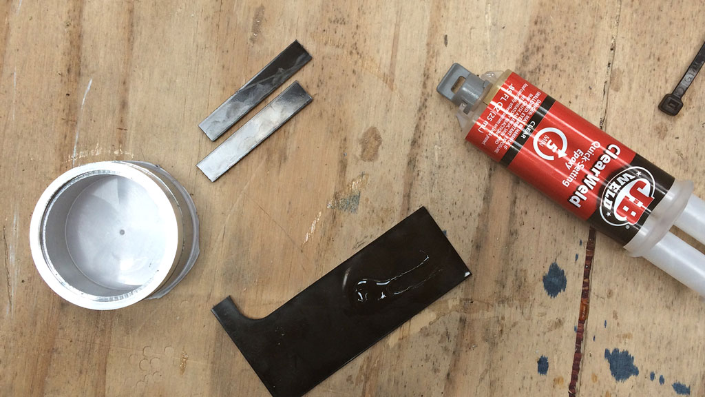
A small step was turned to locate the acrylic base on the bottom of the aluminium body. This ensured that there was extra surface area for the epoxy to act on, and that it was held in place securely (with a huge chunk of steel) while it was curing.
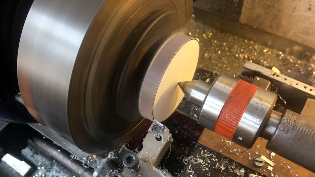
Once the epoxy had cured the new composite body was turned around, chucked from the internal diameter of the bore and the whole OD was turned, then lightly grained with wet and dry paper.
Electronics wise the required illumination will be provided by three generic WS2812 "neopixels", controlled by a Wimos D1 mini ESP8266 breakout board. Each LED sits in a hole partly drilled through the acrylic base - this allows the light to actually make its way out to the edges rather than simply shining straight through the clear acrylic onto the surface it is resting on.
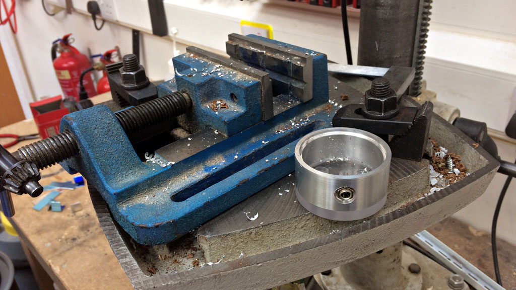
To keep the LEDs in place a small divider was cut on the laser cutter, then coated in aluminium foil to keep as much reflected light going back down and out rather than illuminating the top surface. Once the light assembly was in place the correct height for the power entry socket could be determined and then drilled. Don't mind the rough look of the edges here, once everything was finished it was off to the lathe for a final touch with sandpaper!
![]()
Making it actually work
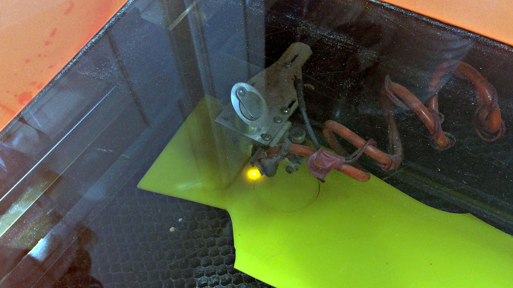
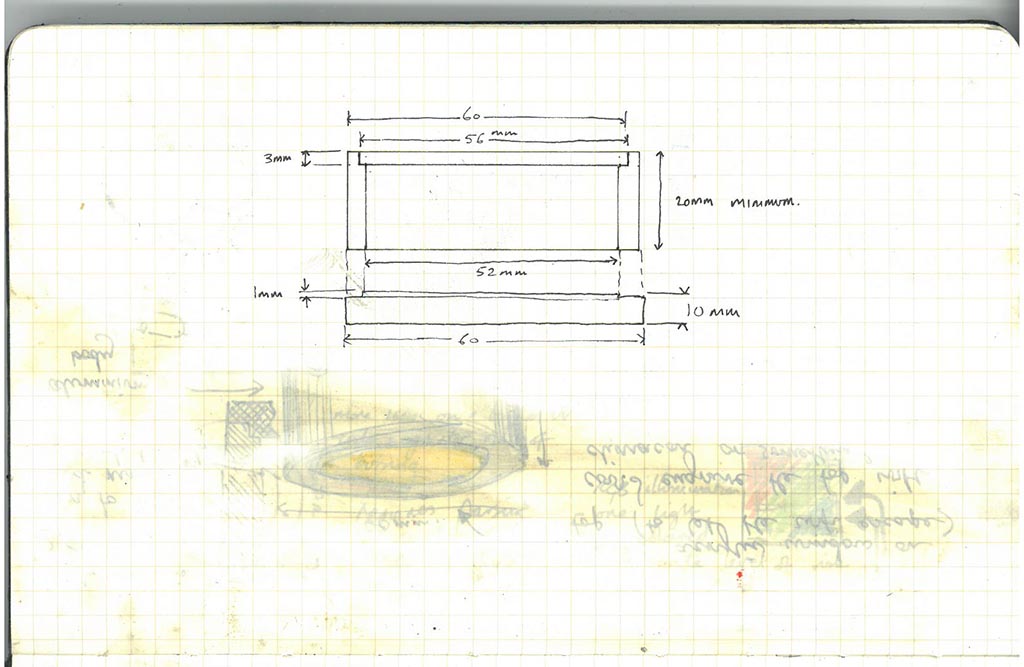
Everything up to now has just been the mechanical aspect: this overbuilt light could be used for anything, and still could be. What actually makes it useful as a UV index indicator (or, "sunburnometer") is the electronics and subsequent firmware. First up, check that the electronics work in the enclosure and that the wifi will still work with the turned plastic lid on the top.
![]()
Fantastic.
The UV index data is provided by Dark Sky using their incredibly easy to use API. Be warned though, their UV index data is still in Beta and as such is not a documented part of their API. There are other providers who can provide the data, such as UVIMate (Free!), Open Weather Map (£££) and the EPA (US only).
I did have trouble getting the ESP8266 to talk to their server, but I think that's an issue on my end, in particular with the method I'm using to GET request the data I want and the amount of data that's returned. In the interests of getting the project complete in one day (and not fighting with spurious ESP8266 resets) I cached the UV index and presented it elsewhere in a much smaller JSON file:
{"uvindex": 3}
The ESP8266 had no trouble at all coping with data this simple, although I did use the JSON library to facilitate further expansion.
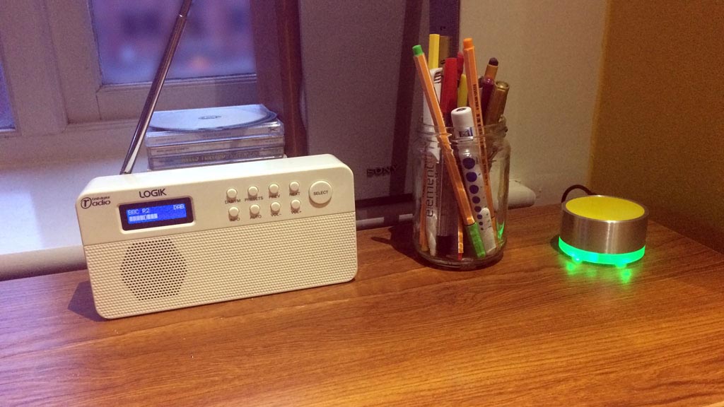
Currently the device will only show the current UV index, in colours taken from the United States's EPA website, which helpfully correspond with colours commonly associated with hazard (except perhaps for Violet, which thankfully we don't get here in the UK). This is the minimum viable product that I set out to produce in a day, so I'm happy to have completed it to this point.
It's a bit simple... What could be improved?
Future enhancements will probably include the ability to display the day's forecast. Sure, it's fine showing me that there is low risk of burning now, as I'm heading out for work, but what about later on in the afternoon when I'm heading home again?
Varying the intensity of the light would also be useful - at night I don't particularly need anything super-bright light to overcome ambient light - so perhaps brightness can be varied by time.
At the moment the UV index displayed doesn't take into account the weather conditions. Does it need to? If it's going to be stormy and rainy, then should there be a lower value displayed? Perhaps this could be cause to display something more dimly.
The top is just resting in its recess (quite snugly, there's a slight pneumatic fit) so there is currently access to the USB port for reprogramming. In the future when this is sealed up it would be handy to implement OTA programming. I'll put the (horribly dirty) code up on GitHub soon.
Done!
It's always important to start with an idea of what you want to produce, even if it means you don't actually make anything for the first hour or so. Be it detailed plans, or just a sketch, having something helps!
The overall take-away message from this one-day project? Get a bigger drill bit. Boring is, well, boring!