Inverted tooling on the Boxford TCL160
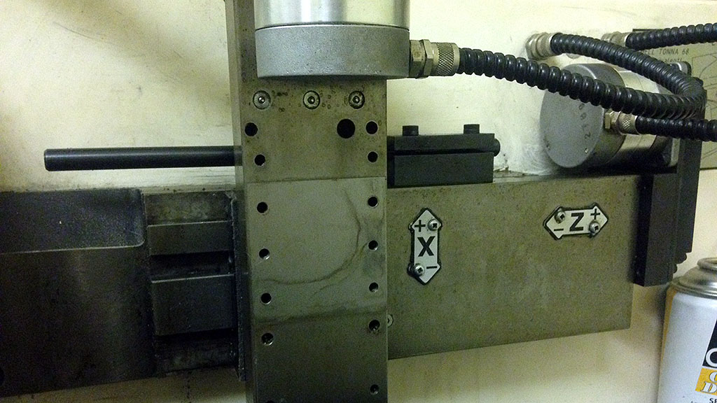
20 May 2016A quirk of small Boxford CNC lathes is that, contrary to what appears to be most other CNC turning machines, they use their back-side tooling the "right" way up - with their insert facing away from the bed. This gives the advantage of allowing the user to see the tool edge clearly but also has the critical disadvantage that it requires left-hand oriented tools.
Typically this isn't an issue. Normal turning tools are available readily in left and right handed versions, but when it comes to specialist tooling (like those used for threading) things can start to get very expensive, very quickly.
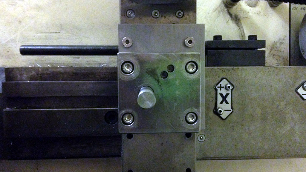
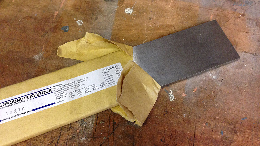
Using the Quick Change Tool Post (QCTP) currently fitted to this lathe it isn't possible to raise a 12 mm shank tool far enough from the bed to properly centre on the spindle axis. To solve this problem I am going to insert a spacer made from 10 mm thick precision ground tool steel in between the tool post pillar and the cross slide. This will allow the height adjusting thumbscrew on the tool holders enough vertical room to compensate.
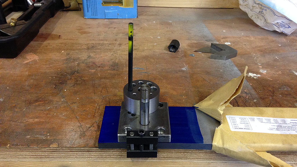
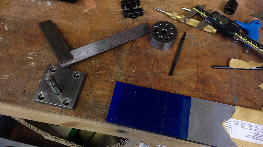
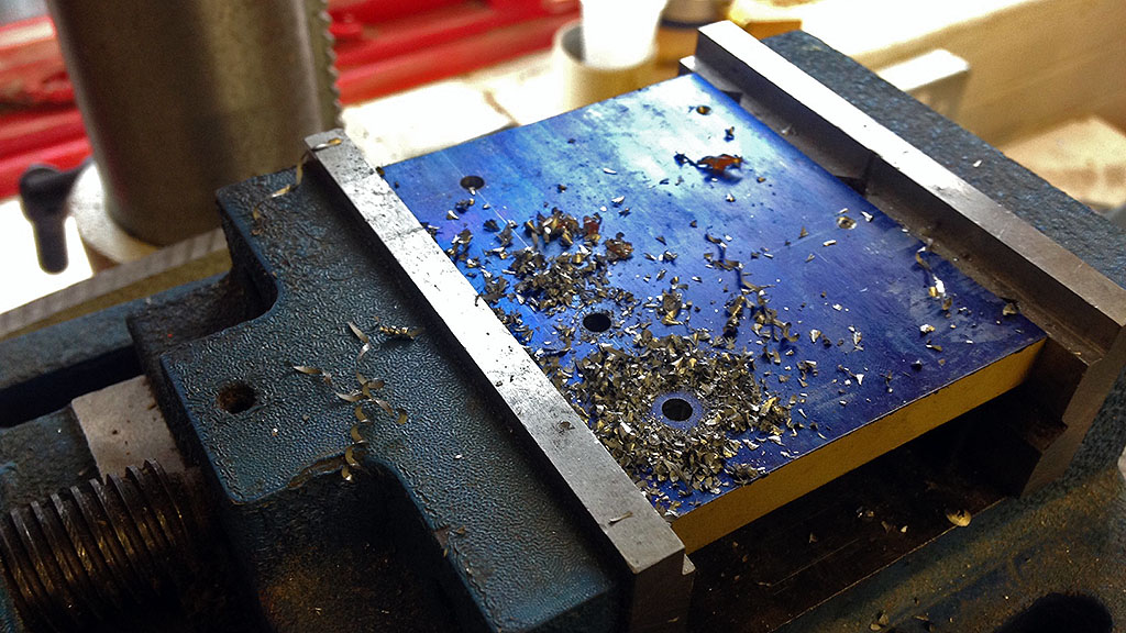
Using the current QCTP pillar as a template a series of holes were transfer punched into the layout-dyed surface of the steel. There wasn't a lot of material at the bottom of the existing counterbored holes so despite the punch being a snug fit I needed a bit of extra support from a DIY tapping guide to make sure it was held vertically.
The lathe cross slide has a number of tapped holes on its upper surface to allow for a variety of different tool mounting options, including the QCTP, turret and gang tooling. To add as much support to the tool I'm extending the plate upwards to utilise the two M5 threaded holes at above the bare clean patch of metal shown in the image above. The two rows of holes are spaced at 20 mm intervals so the additional points were marked out and centre-punched.
The lower holes are a different thread diameter so I am not including them in the area covered by the plate.
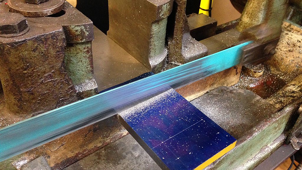
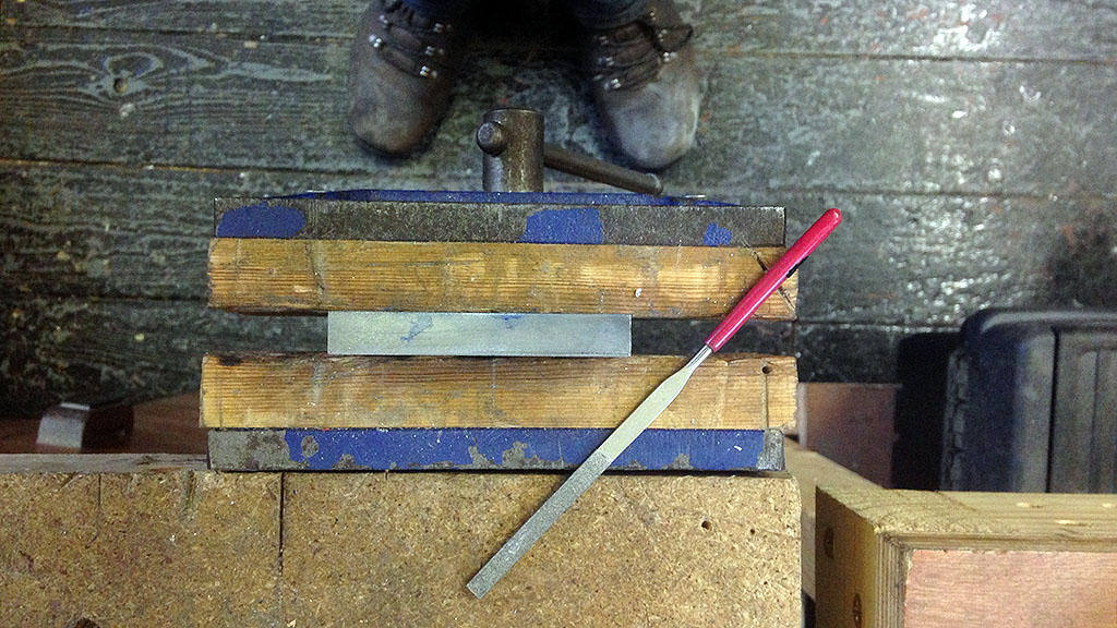
After cutting off with the power hacksaw (much more accurate than doing it by hand) the small burr was removed with a normal file and the edges were broken gently with a small diamond file. 5.5 mm clearance holes for the M5 mounting screws were drilled and the edges deburred using a countersink.
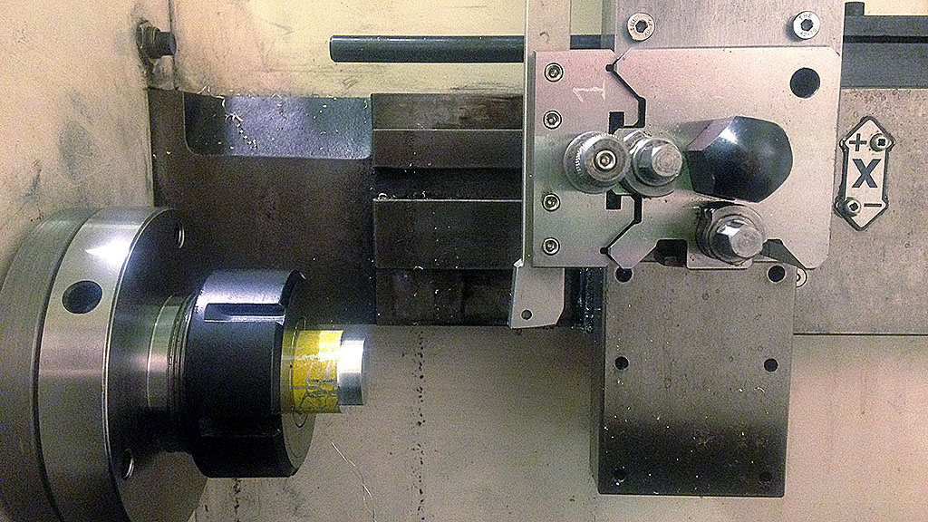
Unfortunately I was only able to get flat stock in dimensions to the closest 10 mm. This particular stock is 70 mm wide, the next size down was 60 mm. The design of the Z axis means that this edge hanging over the back will never collide with anything, but it certainly does look a bit unsightly. If I ever get access to a full size mill I will definitely trim it down to 65 mm wide to match the rest of the cross slide. For the time being though it's not hurting anybody.
The only thing left is to align the toolpost with the spindle (by taking up the slop in the clearance holes) so drills can be used without rubbing a tapered hole.